A Data Flow Diagram (DFD) is a graphical tool used to represent how data moves through a system. It shows data inputs, outputs, data stores, and the processes that transform the data.
This guide provides everything you need to know about data flow diagrams, including definitions, history, and symbols and notations. You'll learn the different levels of a DFD, the difference between a logical and a physical DFD and tips for making a DFD.
DFD is a system created by analysts based on interviews with system users. It is determined for system developers, on one hand, project contractor on the other, so the entity names should be adapted for model domain or amateur users or professionals.
RPO Codes VIN Decoder - Find out what options your GM Chevy Buick Cadillac vehicle is equipped with - GM Chevrolet Buick Cadillac - Regular Production Option
A data flow diagram (DFD) maps out how information, actors, and steps flow within a process or system. It uses symbols to show the people and processes needed to move data correctly.
A data flow diagram (DFD) illustrates how data is processed by a system in terms of inputs and outputs. As its name indicates its focus is on the flow of information, where data comes from, where it goes and how it gets stored. Data flow diagrams became popular in the 1970s in software development.
A Data Flow Diagram (DFD) is a traditional way to visualize the information flows within a system. A neat and clear DFD can depict a good amount of the system requirements graphically.
Data flow diagram (DFD) is a graphical representation method used to depict the flow, storage, processing and interaction between external entities of data in a system.
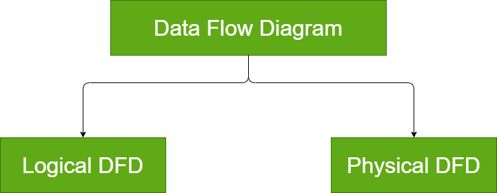
Data Flow Diagram ( DFD) are visual maps that provides a clear understanding of how information moves within a information system. There are two types of Data Flow Diagrams (DFD) that are physical and logical DFD.
 Data Flow Diagram ( DFD) are visual maps that provides a clear understanding of how information moves within a information system. There are two types of Data Flow Diagrams (DFD) that are physical and logical DFD.